Navigation
- About
- FAQ
- Disclaimer
- Blog
- Contact
TOPICS COVERED IN THIS MODULE
BLOCK ‘E’ – Makes up 9% of the industrial electrician 442A C of Q exam and 10% of the Construction and maintenance electrician 309A C of Q exam.
FIRE ALARM SYSTEMS
2018 CEC section 32 (pg.280)
CONDUCTORS OF A FIRE ALARM SYSTEM
FIRE ALARM WIRING METHODS
FIRE ALARM CIRCUIT BREAKER
A fire alarm system shall be supplied by a totally separate circuit. The overcurrent device (Circuit breaker) shall be identified as the fire alarm power supply and the circuit breaker shall be coloured red and be lockable in the ON position.
BASIC FIRE ALARM SYSTEM
A basic fire alarm system consists of:
TYPES OF FIRE SYSTEM ALARMS
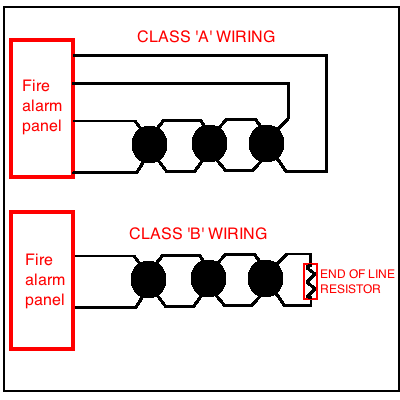
ADDRESSABLE CLASS ‘A’ WIRING
As shown above Class ‘A’ wiring has 4 wires (2 pairs) connected to the fire alarm panel. If there is a broken wire in the circuit the panel can still communicate with the devices via a back feed on the other pair of wires connected to the panel. This arrangement provides redundancy into the system.
Devices installed in Class ‘A’ loops are addressable and are programmed with their own unique address and report their status directly with the fire alarm panel.
CONVENTIONAL CLASS ‘B’ WIRING
As shown above with class ‘B’ wiring the devices are daisy chained together, if there is a break in the circuit any downstream devices will be inoperable because there is no redundancy with this type of wiring.
Devices installed in Class ‘B’ loops are NOT programmable but rather send a fire alarm condition to the panel on a switch closure or change of state.
A supervisory current flows through the EOL at the end of the circuit and monitors the loop wiring integrity, if the panel receives the supervisory current all wiring is OK, if it does not receive the supervisory current it assumes a problem with the circuit and initiates a loop trouble alarm.
END OF LINE RESISTOR (EOL)
The fire panel circulates a supervisory current to ensure the loop circuit is intact, the end of line (EOL) resistor limits the panels supervisory current, if a break in the circuit exists the panel will not see the supervisory current come back and will assume there is a problem with the loop circuit (open cct) and will initiate a trouble alarm.
ANCILLARY DEVICE
Is a device that is connected to and activated by the fire alarm system but is not a part of the fire alarm system. For example; magnetic door locks, door holders, remote LED indicators and smoke control fans etc.
TAMPER SWITCH
If a tamper switch is activated it will send a trouble alarm to the FAP, these switches are on devices that should not be opened by untrained personnel. For example a tamper switch is on the connection box of a valve position switch for a fire water valve. A tamper switch alerts personnel of someone tampering with the device.
SMOKE DETECTORS
The two types of smoke detectors are ionization and photoelectric.
Ionization detectors contain a small amount of radioactive material in the sensing circuit. Photoelectric detectors use a light source and a sensing chamber, when smoke enters the chamber the light is reflected on to the sensor and an alarm is initiated.
SINGLE STAGE FIRE ALARM
When the fire system is activated by an initiating device (smoke/heat/pull stations etc) and the fire alarm signal is immediately transmitted by notification appliances (strobe/horns/speakers) throughout the building to warn occupants that a fire emergency exists.
TWO STAGE FIRE ALARM
When fire alarm is initiated an alert signal is first activated (first stage) that alerts staff of a possible fire condition, staff are to immediately investigate the alarm and if a fire exists they are to activate the fire alarm signal (second stage), if it is determined no fire condition exists the alert alarm can be reset. (Two stage fire alarms are common healthcare facilities)
VERIFICATION OF FIRE ALARM SYSTEMS
(ULC = underwriters laboratories of Canada)
CAN/ULC -S524 – Installation standards for fire alarm systems. S524 makes reference to the CEC for wiring and raceway requirements for installation of fire alarm systems.
CAN/ULC -S536 – Inspectionand testing standards for fire alarm systems
CAN/ULC -S537 – Verification standards for fire alarm systems.
Refer to Rule 32-200 ‘installation of smoke alarms and carbon monoxide alarms in dwelling units’ (pg.281 2018 code). (smoke alarm and carbon monoxide alarms now has its own heading in 2018 code book).
32-200 (e) (pg.281 2018 code) states you can connect a smoke alarm or combination smoke/carbon monoxide alarm to a circuit protected by a ground fault circuit interrupter or arc fault circuit interrupter if it has an integral battery as a secondary supply source.
32-200 (b) (pg. 281) : From the overcurrent device of the branch circuit to the smoke or carbon monoxide alarm should be continuous with no means of disconnection.
2018 code book Section 56 (pg.333)
OPTICAL FIBER CABLE
A cable consisting of one or more optical fibers that transmits modulated light for the purpose of control, signalling , or communication.
During installation of fiber optic cables avoid kinking the cable as this can damage the fibers.
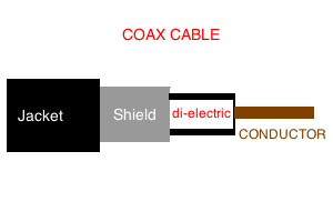
Coax is used to transmit radio frequency signals. Applications include radio transmission, receivers, computer network and cable television signals.
A coax cable connector and shield should have electrical continuity because the shield eliminates electrical noise, this can be checked with a multimeter on ohms to ensure continuity.
After the installation of a coax cable in a network use a LAN TESTER to test it.
END