The binary system (base 2) expresses information by using combinations of the digits 1 and 0. Binary system is well suited to logic systems (computers, control systems, PLC’s) where many devices have only two states on or off (switches, solenoids, relays etc..). As with the decimal (base10) system the value of each binary digit is determined by its position in the overall number, as shown below.
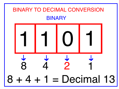
BINARY TO DECIMAL CONVERSION
When converting binary to decimal start at the far right binary bit and assign a value of decimal ‘1’ to it, then move to the next bit to the left and double the decimal value for that bit (2) and continue to move to the left and keep doubling the decimal number for as many binary bits as you have in the question as shown above.
Once you have done this for each bit, you now have a decimal number associated with each digital bit so add up all the decimal numbers that have a binary ‘1’ assigned to them (as shown above 1,4,8) and ignore the binary ‘0’ decimal numbers (2) . Adding up all the binary ‘1’ decimal equivalents we get from right to left 1 + 4 + 8 = 13.
Therefore binary 1101 = 13.
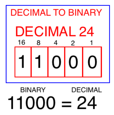
DECIMAL TO BINARY CONVERSION
Start by writing out the decimal equivalents of the binary positions starting from right to left as shown above (1,2,4,8,16). To achieve a decimal 24 we need a 16 and an 8, therefore the binary number( 1 or 0) associated with 16 and 8 should be a binary ’1’. That leaves us with 11000 = 24.
SERIAL COMMUNICATION
RS-232 is a standard for serial communication and transmission of data.
Pin 2 on RS-232: Used to transmit signals.
Pin 3 on RS-232: Used to receive signals.
Pin 7 on RS-232: Signal ground.
Communication systems are affected by noise from other cables or circuits. To eliminate noise ensure that adequate separation ( 2018 CEC Rule 60-308 pg.342) is maintained from power circuits when installing communication systems.
OSCILLOSCOPE
Is an electronic device used to display amplitude (y-axis) and time (x-axis) characteristics of a waveform. Using the grid (Volts/div and Time/div) of an oscilloscope you can determine the voltage and time period (T) of a waveform. Once you know the time period (T) you can determine the frequency (F) of a waveform.
F = 1/Time, T = 1/Frequency. Time period (T): is the amount of time for one complete cycle to occur.Frequency (F): is the number of cycles per second.
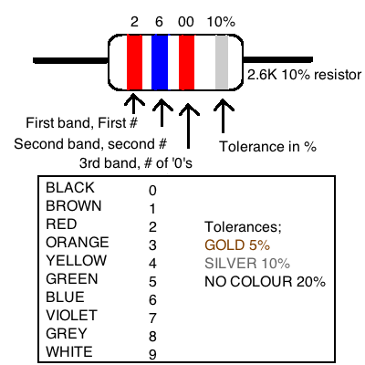
RESISTOR COLOUR CODES
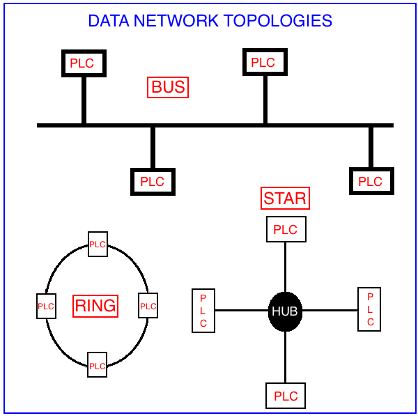
DATA NETWORK TOPOLOGIES
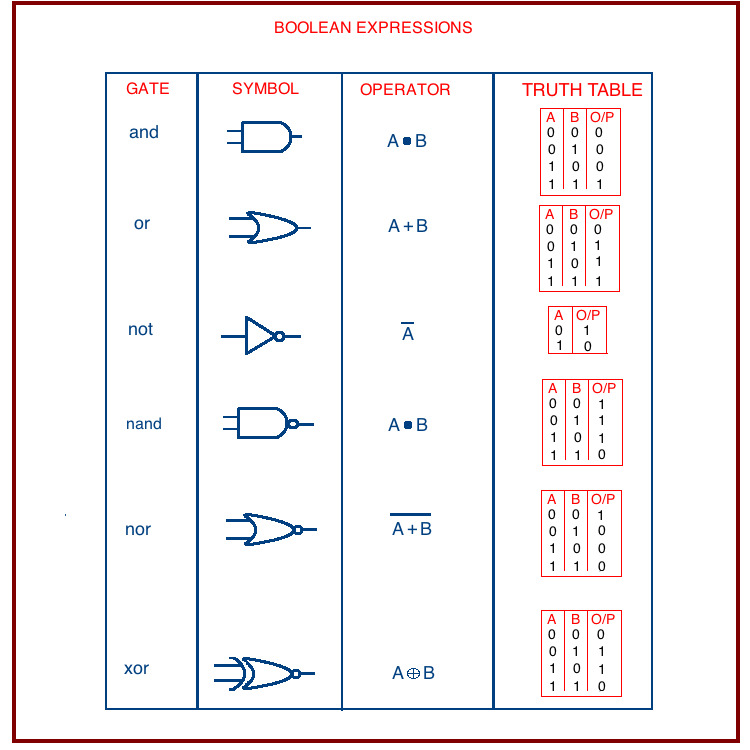
LOGIC GATES
Transistor Transistor Logic (TTL): Operates at a voltage of 5v
CMOS: Operates at a voltage of 3.3v
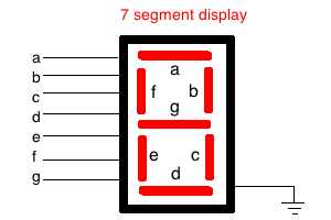
7 SEGMENT DISPLAYS
A 7 segment display requires 8 conductors, 7 input wires and a ground wire as shown below.
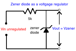
ZENER DIODE
A zener diode can be used as a simple voltage regulator as shown below
OPTO-COUPLER/OPTO-ISOLATOR
This device transfers electrical signals between two isolated circuits by the use of light. They prevent high voltages from adversely affecting the system receiving the signal (low voltage circuits).
CEC SECTION 60 – ELECTRICAL COMMUNICATION SYSTEMS
SEPARATION OF COMMUNICATION SYSTEM CONDUCTORS
(insidebuildings)
Refer to 2018 CEC 60-308 and 60-318 (pg.342)
COMMUNICATION SYSTEM CONDUCTORS
shall be separated at least 50mm from any insulated conductor of a Class 1 circuit or any electric light or power system operating at 300v or less, and shall be separated at least 600mm from any insulated conductor or an electric light or power system operating at more than 300v
COMMUNICATION CONDUCTORS UNDER RAISED FLOORS
Conductors of Communication systems shall be permitted to be installed without additional mechanical protection under a raised floor, provided that,
Raised floor is suitable non – combustible construction
Minimum separation of 50mm is maintained from power circuits,
Conductors serve the equipment located only on the floor above the raised floor, where the space under the raised floor is used as an air plenum.
 When converting binary to decimal start at the far right binary bit and assign a value of decimal ‘1’ to it, then move to the next bit to the left and double the decimal value for that bit (2) and continue to move to the left and keep doubling the decimal number for as many binary bits as you have in the question as shown above.
Once you have done this for each bit, you now have a decimal number associated with each digital bit so add up all the decimal numbers that have a binary ‘1’ assigned to them (as shown above 1,4,8) and ignore the binary ‘0’ decimal numbers (2) . Adding up all the binary ‘1’ decimal equivalents we get from right to left 1 + 4 + 8 = 13.
Therefore binary 1101 = 13.
DECIMAL TO BINARY CONVERSION
When converting binary to decimal start at the far right binary bit and assign a value of decimal ‘1’ to it, then move to the next bit to the left and double the decimal value for that bit (2) and continue to move to the left and keep doubling the decimal number for as many binary bits as you have in the question as shown above.
Once you have done this for each bit, you now have a decimal number associated with each digital bit so add up all the decimal numbers that have a binary ‘1’ assigned to them (as shown above 1,4,8) and ignore the binary ‘0’ decimal numbers (2) . Adding up all the binary ‘1’ decimal equivalents we get from right to left 1 + 4 + 8 = 13.
Therefore binary 1101 = 13.
DECIMAL TO BINARY CONVERSION
 Start by writing out the decimal equivalents of the binary positions starting from right to left as shown above (1,2,4,8,16). To achieve a decimal 24 we need a 16 and an 8, therefore the binary number( 1 or 0) associated with 16 and 8 should be a binary ’1’. That leaves us with 11000 = 24.
 Transistor Transistor Logic (TTL): Operates at a voltage of 5v
CMOS: Operates at a voltage of 3.3v
Transistor Transistor Logic (TTL): Operates at a voltage of 5v
CMOS: Operates at a voltage of 3.3v
 ZENER DIODE
A zener diode can be used as a simple voltage regulator as shown below
ZENER DIODE
A zener diode can be used as a simple voltage regulator as shown below
 OPTO-COUPLER/OPTO-ISOLATOR
This device transfers electrical signals between two isolated circuits by the use of light. They prevent high voltages from adversely affecting the system receiving the signal (low voltage circuits).
OPTO-COUPLER/OPTO-ISOLATOR
This device transfers electrical signals between two isolated circuits by the use of light. They prevent high voltages from adversely affecting the system receiving the signal (low voltage circuits).
 CEC SECTION 60 – ELECTRICAL COMMUNICATION SYSTEMS